-
Notifications
You must be signed in to change notification settings - Fork 6
Kit Assembly Notes


Additional assembly info:
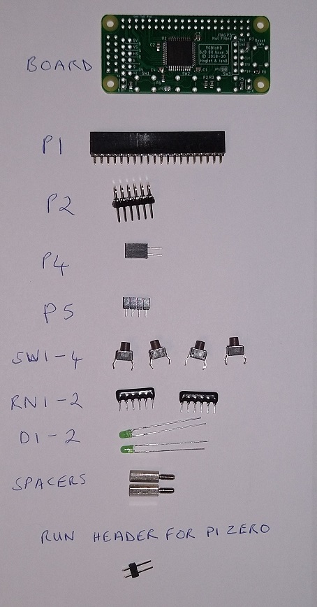
P2 should be fitted slightly slightly away from the pcb to allow clearance for an IDC header.
To avoid errors, I have tack soldered the corners of P2 in the correct position.
Cut off the legs of the 4 switches flush with the PCB before soldering so there is no protusion which would make it difficult to plug an IDC header into P2
The cathode of the leds is marked with a "K" and is the shorter lead


Additional assembly info:
IMPORTANT
The long pin side of P2 must be soldered in the board. It is a low profile connector and the short side of the pins mate with the connector on the main board.
Tin the pads of P4 first, then push onto the pins before soldering as that will keep it centred. (Note the orientation and position of pin1)
Fit Long ends of P6 & P7 into pcb same as P2 above, then cut off the other ends of the pins at the plastic. They are intended to act as feet resting on the camera connector to stop the board making contact with the Pi zero.

Additional info:
Solder the supplied two pin header into the "RUN" connector on the Pi zero. This connects the reset signal to the main board.
The case is supplied with 4 bolts, use two of them to screw the Pi zero into the case and use the two supplied spacers in the other two holes.
(File approx 0.5mm off the end of the spacers to ensure they don't push out of the bottom of the case)
Use the two remaining bolts to screw the main board into the spacers
Drilling Template for the case
If you have ordered just the main board you will be supplied with a 12 way IDC header and 12 way ribbon cable:

This should be connected as follows:
| RGBtoHDMI 12 way IDC | 6 way DIN | Notes |
|---|---|---|
| Pin 1 X1 | ||
| Pin 2 X2 | ||
| Pin 3 GND | Pin 5 | |
| Pin 4 Bgreen | ||
| Pin 5 Bred | ||
| Pin 6 Bblue | ||
| Pin 7 RED | Pin 1 | |
| Pin 8 HSYNC | Pin 4 | |
| Pin 9 GREEN | Pin 2 | |
| Pin 10 VSYNC | ||
| Pin 11 BLUE | Pin 3 | |
| Pin 12 +5V | Pin 6 | Leave unconnected if powering Pi externally |
If you have ordered an analog board as well, you will be supplied with a 6 way IDC header and 6 way ribbon cable:

This should be connected as follows:
| RGBtoHDMI 6 way IDC | 6 way DIN | Notes |
|---|---|---|
| Pin 1 GND | Pin 5 | |
| Pin 2 SYNC | Pin 4 | |
| Pin 3 BLUE | Pin 3 | |
| Pin 4 GREEN | Pin 2 | |
| Pin 5 RED | Pin 1 | |
| Pin 6 +5V | Pin 6 | Leave unconnected if powering Pi externally |
Construction (current designs)
- Bill of Materials (12-Bit Board)
- Bill of Materials (12-Bit Extender)
- Bill of Materials (Analog Board)
- Bill of Materials (TTL Buffer Boards)
- Bill of Materials (Pi Zero)
- Cables
- Assembled boards for sale
Construction (older designs)
- Bill of Materials (6/8-Bit Board)
- Bill of Materials (6-Bit Board)
- Bill of Materials (3-Bit Board)
- Bill of Materials (Atom Board)
- Assembly Notes (Atom Board)
- CPLD Programming
User Documentation