Skip to content
New issue

Have a question about this project? Sign up for a free GitHub account to open an issue and contact its maintainers and the community.

By clicking “Sign up for GitHub”, you agree to our terms of service and privacy statement. We’ll occasionally send you account related emails.

Already on GitHub? Sign in to your account

Custom Profile (Osborne 1) #31

Open
dadecoza opened this issue Jun 11, 2024 · 17 comments
Open

Custom Profile (Osborne 1) #31

dadecoza opened this issue Jun 11, 2024 · 17 comments

Comments

@dadecoza
Copy link

I'm having an issue creating a custom profile,

According to the Osborne 1 Technical Manual the settings should be as follows ...

Width in pixels: 416
Height in pixels: 240
Dot clock: 8Mhz

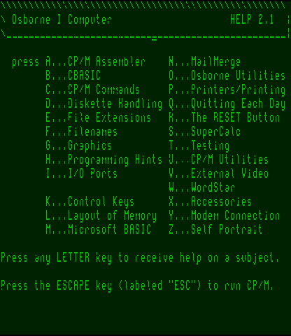
However the output I get looks like ...

Osborne Settings

Osborne Result

Any tips?

Thanks!

@IanSB
Copy link
Owner

IanSB commented Jun 12, 2024

@dadecoza

According to the manual you linked, the actual crystal frequency is 15.9744Mhz:
osborne

So the "8" Mhz dot clock is 7987200 not 8000000 which might fix the mis-sampling but it looks like the image is shifted which can happen if the Hsync is wider than than the blanking period and not a normal hsync.
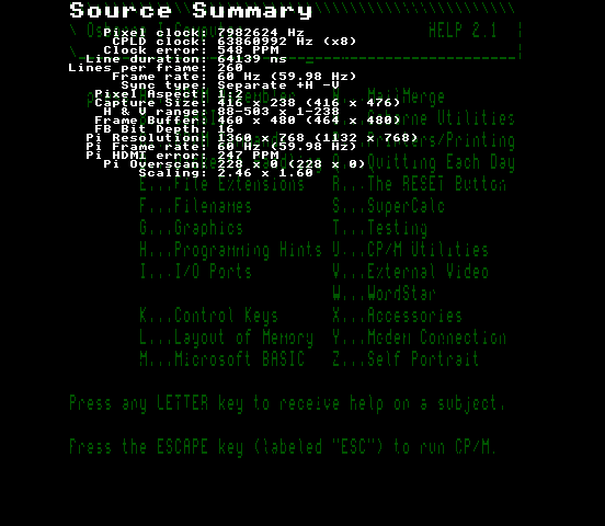
After tweaking the clock, can you post screencaps of the source summary page in the info menu and the geometry and sampling menus.
Press the Up and Down buttons together to screencap a menu, files in /captures on the SD card

@IanSB
Copy link
Owner

IanSB commented Jun 12, 2024

@dadecoza

Looking at this further, the hsync signal is, as I suspected, not a proper hsync which usually lasts for 4.7uS and it is instead a square wave:
osbornehsync
The profile is currently triggering off the edge in the middle of the screen so try changing the sync edge setting in the sampling menu which will make it trigger off the other edge.

@dadecoza
Copy link
Author

Progress!
Osborne Leading Edge
Osborne Source Summary

Changing the edge to trailing fixed the alignment.

However it is still a little noisy.

@IanSB
Copy link
Owner

IanSB commented Jun 12, 2024

@dadecoza

Have you tried adjusting the line length + or - 1, 2 or 3
(If the screen all goes noisy instead of clean on one of those settings that is probably the right value but you then have to run the calibration)

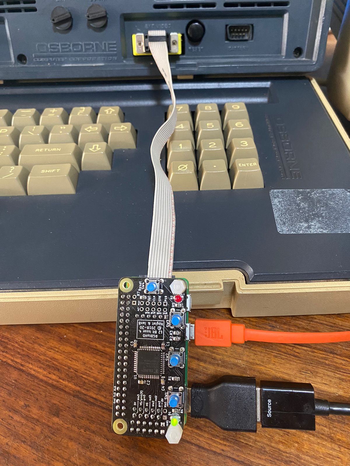
Also where have you connected the RGBtoHDMI inputs?

@dadecoza
Copy link
Author

I have tried playing with the line length but it did not help much. Not giving up though will mess around some more,

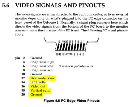
As for how it is connected ...

Osborne Hardware
Osborne Document

Osborne 1 RGBtoHDMI
VSync VSync
HSync HSync
Video Out Grn3
Gnd Gnd

@IanSB
Copy link
Owner

IanSB commented Jun 12, 2024

@dadecoza
The video output is really an analog signal which is at least one reason why the signal is noisy as you are feeding that into a digital input. Looking at the schematic:
osborne-video

The video is fed from a contrast control which will vary the voltage level and also the low intensity setting will reduce the voltage level too when active so characters with that attribute may appear noisy or blank.
Normally I would suggest using an analog interface addon but that can only use composite sync and in this case you can't easily combine the H and V sync signals with diodes to make composite sync because the Hsync signal is a very non-standard square wave.

It should be possible to modify an analog interface to inject separate syncs if you want to go that route but to get this working properly with the digital board you would have to connect internally to the inputs of those four open collector (O.C.) drivers shown above (Hsync, and Vsync with Grn3 and Grn2 connected to the video and intensity signals)

Turning up the contrast to max might help but the low intensity setting is still going to reduce the voltage level anyway.

@dadecoza
Copy link
Author

Hi Ian,

Thank you so much for your patience and detailed explanation.

As you probably gathered my knowledge of how video output work is very limited. At least I now have an explanation for the noise, and it really is not that bad,

Thanks again and feel free to close this ticket,

@IanSB
Copy link
Owner

IanSB commented Jun 12, 2024

@dadecoza

Can you post your current profile.
Will either be in /Saved_profiles if you made any changes after creating your custom profile or if not then it will be in /Profiles

@dadecoza
Copy link
Author

Custom_Profile_0_.txt

as requested...

@IanSB
Copy link
Owner

IanSB commented Jun 12, 2024

@dadecoza
There were some settings in your profile that needed tweaking:

As the hsync edge is so close to the active video that can cause problems so I switched from Leading to Leading+Delay (that also meant changing to 3bpp capture). Plus I set the pixel aspect ratio and the palette to mono.
It should still be possible to get this working with intensity although the connections might have to be different with a custom palette.

BTW the line length of 512 looks correct as it is a nice round binary number so all the noise is probably due to the analog signal.

Can you check that this profile is still OK and if so I will add it to future releases as it at least gets the timing correct so would be a good starting point for a fully correct profile:

Osborne_1_(No_Intensity).txt

Put it in this folder on the sd card:

\Profiles\6-12_BIT_RGB\_Other

reboot and select it from 'Other' in the profile menu

@dadecoza
Copy link
Author

osborne_1_new_profile

Looking good!

@dadecoza
Copy link
Author

intensity
capture1

Seems the intensity bit is more important than I thought ... In the above example the CP/M logo has a lower intensity and is completely absent from the RGBtoHDMI screen capture.

@IanSB
Copy link
Owner

IanSB commented Jun 12, 2024

@dadecoza

Seems the intensity bit is more important than I thought ... In the above example the CP/M logo has a lower intensity and is completely absent from the RGBtoHDMI screen capture.

There are several options to implement this:

  1. Internal TTL connection
  2. Use an RGBS analog addon board (some mods will be required to get the separate vsync in)
  3. Use a mono/lumacode board. This is a board that contains the CPLD and part of the analog board, enough for multi level mono signals and it is mainly used with c0pperdragon's lumacode adapters to get RGBtoHDMI working with systems like the C64 / C128, Atari 800 & 2600, TI99 etc but it can be configured by using solder jumpers to input analog video and separate H and V syncs on a 3.5mm TRRS connector and that option was included for this kind of situation. (I have tried that on my Commodore PET.)
  4. Use a couple of analog comparators on a breadboard between the Osborne 1 socket and the RGBtoHDMI to extract the two analog video levels. (This is effectively what the analog or mono/luma board does)

@dadecoza
Copy link
Author

Great thanks. :)

Our local vintage computing group is planning an "Osborne repair day" and I will then take the opportunity to try some of your suggestions. The repair day is also the reason I wanted to get the RGBtoHDMI working so that we can bench test/debug the main boards outside of the case.

@dadecoza
Copy link
Author

capture2

But man it still looks great!

@IanSB
Copy link
Owner

IanSB commented Jun 12, 2024

@dadecoza
Here is a speculative profile for intensity:
Osborne_1_(With_Intensity).txt

I had to revert to Leading rather than Leading with delay as that only works at 3bpp and intensity support requires 6bpp
Can you check this still works. The image will be dimmer as there is no intensity bit until you connect that to Grn2

@dadecoza
Copy link
Author

capture0
Amazing

Sign up for free to join this conversation on GitHub. Already have an account? Sign in to comment
Labels
None yet
Projects
None yet
Development

No branches or pull requests

2 participants